### THIS IS AN IMPORTED PAGE ####
|
6 Elements on 50 MHz / 6 metres de VK4ADC or a 50 MHz / 6 metre J Pole design
----------------------------------------------------------------------------------------------------------
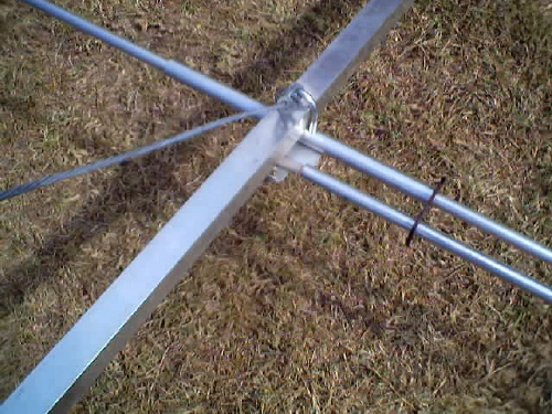
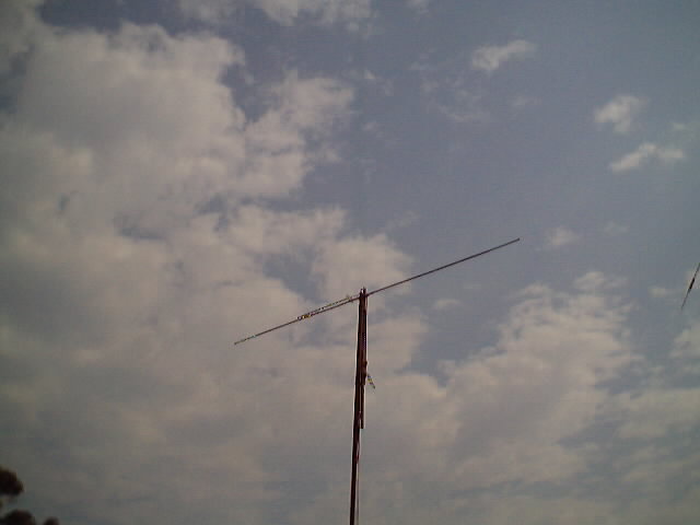
This is a design based on the QuickYagi 4 software by WA7RAI with some changes for practical reasons. The beam uses 6.5 metres of standard 25mm square boom, 12mm diameter elements without tapers, easy U clamp to boom element mounting and simple gamma matching using coax inner into an aluminium tube - no special capacitors to buy or waterproof. The actual boom length used is 6.3 metres and all parts are readily available. Construction details are shown below. The design values were 12.0 dBi gain and 35dB front/back with a nominally wide bandwidth, 3dB beam width of +/- 47 degrees, on-boom element mounting, resulting feed impedance calculated at 16.8-j0.9 ohms. After completion, the yagi was compared to a standard 1/2 wave dipole, also gamma matched, which was alternated on the mounting pipe for comparative received signal level measurements from the same signal source. The VSWR was 1.05:1 after careful adjustment of the overlap 'capacitor' and the position of the shorting strap (inductor). Measurements with attenuators and a receiver calibrated in dBm indicated between 11 and 12dB gain (referenced to the dipole) and a front/back of 29 - 30dB. Nulls off the 'rear quarters' were greater than 40dB.
Mouse-over each picture to see largerl :
The test signal source was a 50.000MHz 14 pin DIL TTL oscillator in a diecast box, with 5 volt 78L05 regulator, power switch and 9V alkaline battery. The output from pin 8 is coupled by capacitor to a BNC female connector. A 1/2 wave wire dipole fed at the centre is connected straight to a BNC plug. This signal source was placed some 100 metres away with the broad side of the dipole oriented toward the test antennas. The receiver used was a Icom R7100 used in conjunction with software which uses calibration tables to read out signal level directly in dBm. Measurements based on attenuator substitution as well as direct level readout were used.
The overall element length measurements are as follows :
Element Spacings (centres) :
There is 100mm length unused at each end of the boom.
CONSTRUCTION :
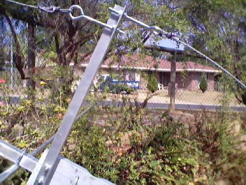
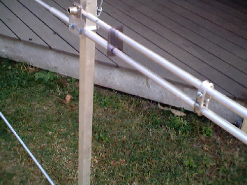
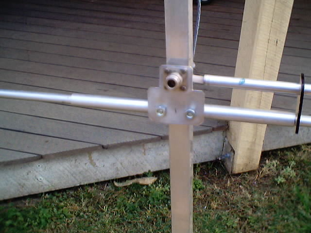
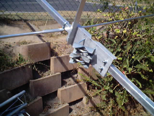
The 3 lengths of 12mm tube will produce the 6 elements plus enough for the gamma matching arm. Cut the reflector and DE from the 1st one, 1st and 2nd directors from the next. The 3rd should produce both director 3 and 4 and the gamma arm tube. Mark the centre point of each element and 125mm either side. Cut the 1500mm of 16mm tube into 6 off 250mm lengths, mark at the centre and 17mm either side. Slide one onto each element so that the marks at the 125mm points are showing and in view equally. Drill clearance holes for the 29mm U clamps through at the points marked 34mm apart on the outer tube. Drill one hole all the way through and put one end of a clamp in it to hold it in place while drilling the second hole. Make sure the clamp will fit properly through the holes. Mark the positions of the elements along the boom starting 100mm from the notional back as per the spacings table. Clamp each element in its correct place. Three further items require manufacture - the boom mounting plate, the anti-sag bar and the gamma match assembly. The boom mounting plate is the flat or C channel and has to have holes drilled for 4 U clamps - 2 x 29mmm and 2 x 50mm. The 2 x 29 mm clamp holes are again drilled about 25mm from each end and 17mm either side of the horizontal centre line (long dimension). The 50mm clamp holes are drilled equidistant either side of the vertical centre line (short dimension) and about 25mm in from the edges - actual hole to hole spacing will depend on the clamps in use. The anti-sag bar is held on to the boom mounting plate by the 29mm U clamp towards the front of the beam. Drill the 1st hole about 25mm from one end and then the second hole 34mm further along. This should match up with the 29mm U clamp holes. Rotate the angle section 90 degrees and drill a clearance hole about 25mm from the other end and a second hole about 30mm further in as well. Insert the eye bolts & nuts one from each side then add the retaining nut with spring washer. This assembly can be added to the beam when the mounting plate is added - at the weight centre point. The gamma match consists of a 490mm length of RG213 inner inside the aluminium tube of the gamma arm. Create a mounting plate with holes to suit the bulkhead style coax connector chosen. Drill the holes for the U clamp at 34mm centres at a distance of 40mm from the line of the centre pin of the coax socket. Assemble the socket to the plate. Cut off 10mm of the inner polythene from the 500mm length and solder it well to the centre pin of the N or SO239 connector, directing it so that it will line up with the direction of the driven element. The shorting strap was created by placing 4 offcuts of the 12mm tube side by side in the jaws of a vice and then using it as a former to shape the flat strip. The extra length is cut off to leave the open ends almost touching. Drill clearance holes through each side to allow the use of a 3/16" roofing screw and nut to tighten the strap around the DE and gamma match tubes. An afterthought was to place an acrylic spacer over both tubes to maintain separation. This was made from a piece of rectangular acrylic cut from a car window weather protector which had seen better days. Tight clearance holes with the correct separation meant that it was simply slid over the tubes before the shorting strap was attached. To attach the gamma match, release the driven element U clamp nuts, slip on the coax connector mounting plate and then replace the nuts. Slide the acrylic spacer along the gamma tube so that it is just near the end and feed the coax inner into the tube as you slide the arm plus spacer along the driven element through the other spacer hole. Starting dimensions for the gamma match are about 30mm of coax inner showing and the shorting strap starting 335mm from the centre line of the DE. Determine the weight centre point of the assembly and mark it. Attach the boom mounting plate at the mark and attach the anti-sag bracket. Add the galvanised wire starting from the DE U clamp making sure you feed the wire back through the hole even if you are using miniature wire clamps. Feed it through the rear-facing eyebolt and cut off with about 150mm to spare. Attach a support wire from the 3rd director back to the forward facing eyebolt again leaving about 150mm to spare. Do not attempt to make the anti-sag adjustments until it is mounted on a vertical pipe and coax is fed to the gamma match and nylon-tied to the boom.
TESTING
Set up the beam so that it is facing straight up in the air with the rear of the beam at least about 600mm above ground and well away from other metal objects. Use ropes to hold it in place while testing as the complete beam is quite heavy and liable to topple. Setting the gamma match.is a simple as using a good VHF SWR bridge in line to the transmitter (10 watts is more than enough - and not on 50.110 ! - try 50.095 or so) and adjusting as follows. Loosen the gamma tube clamp and slide the tube over the coax inner for best SWR. Adjust the DE end of the clamp only as required to extend or shorten the available inductance then re-tighten and slide the gamma arm. At the lowest SWR re-tighten the gamma end of the shorting clamp. Check the SWR at other favourite parts of the band.The SWR on the original beam quickly went to 1.05:1 but note your proximity to it can affect the tuning. The SWR was still 1.05:1 when the beam was shifted from the vertical test position to the gain testing setup at 6 metres above ground.
Bill of Materials : 1 x 6.5 metre length of 25mm Square tubing, 3mm wall (rounded corner variety is cheaper than the standard square corners) for boom
Extract from UKSMG Announcements page : "Antenna" that is not "Antennal" Where the "L" did that "L" come from?? Thanks John ! 28/08/01
Feedback from VK2APG on 31 April 2002 : Built the antenna the previous week, following the construction details exactly, checked the tuning and was easily matched. Put it up in the air and the first contact was ZF1DC. Super-pleased ! Incidentally, both Ron VK4KLC and myself also worked David ZF1DC during the same opening - we are all using the same design yagi - as described above. Yes, it really works and doesn't cost a fortune. Easy to build and gives the right results. 73 Doug
|
||||||||||||||||||||||||||||||||||||||||||||||||||


